
Load from PC
Brownout protection circuit in embedded systems
Hello , everyone .
I'm Shailakadesh Pandey , and welcome to my YouTube channel .
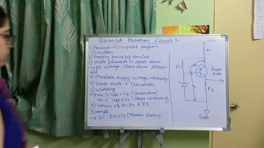
Today's topic is Brown node protection circuit in the embedded systems .
Okay .
So let's get started with the topic .
So basically , what is this Brown node protection circuit ?
See , every processor or controller is having a specified operating voltage that it operates at a particular voltage range .
Okay .
And if , the voltage falls below the specified voltage , then there's a possibility that processor may under undergo unexpected program execution or abnormal behavior .

To avoid this unexpected program execution and abnormal behavior , we are having the brownout hornet protection circuit when it is useful only when the , supply voltage of the processor falls below the threshold value that is specified voltage range .
Okay .
So let's get to the next point .
Battery power devices .
See , this brownout protection circuit , this works on the , devices which operate on the battery .
Okay .
Miss , which are battery powered devices because there's a possibility that battery voltage might drop and during such a situation we will require the brownout protection circuit .
Okay .
Fine .
Now , what does this Brown or protection do ?
Okay .
This Brown or protection , how how does it work ?
See whenever the voltage of the controller or processor falls below the specified voltage .

When it falls below the specified voltage to avoid the unexpected program execution , it resets that processor .
Means when the voltage falls below the threshold value value , it resets that processor .
Okay .
And the processor remains in the reset state till the voltage reaches the value which is above the threshold value or threshold value .
Okay .
And , the reset state , after it when the processor reaches the , specified voltage range , the reset is stopped .
Okay .
It gets back to normal working state .
So to avoid this unexpected abnormal behavior of a processor during the , low power , situations or low voltage situations , we have ground mount protection circuit .
Okay .
Now let's see the working of it .
Now , there are some devices .


There are some , controllers or processors which are having built in ground on protection circuit .
And these built in ground out protection circuit monitors the internal supply voltage of the processor or the controller .
Okay .
There is a supply voltage to every processor of controller to monitor that supply voltage we're having the protection circuit .
Okay .
Now , see , you can see the diagram on the right side .
Okay .
This circuit diagram is of the Brownout protection circuit .
Okay .
Where vcc is the supply voltage , Vbe is the voltage across the transistor and vz is the voltage across the Zener diode .
Okay .
So these are the 3 voltages and according to the values of these 3 voltages , the Brownout circuit protection works .
Okay .
Fine .
Now here , Zener diode transistor .
See .
This is the Zener diode and this is the transistor .

These form the heart of your , Brownian protection circuit .
Zener diode transistor are heart of the Brownian protection circuit .
Now working when we get into the working of this Brown Hall protection circuit .
When the value of the VCC , that is the supply voltage , is greater than the sum of vb and vz , that is the sum of voltage across transistor plus this voltage across diode , okay , then the transistor starts conducting .
See , I've written here .
Vcc greater than bb plus vz transistor conducting .
Okay .
So the transistor starts conducting , and when the transistor is conducting , the voltage drop across it is 0 indicating conducting .
What does that mean ?
When the supply voltage VCC is conducting .
What does that mean ?
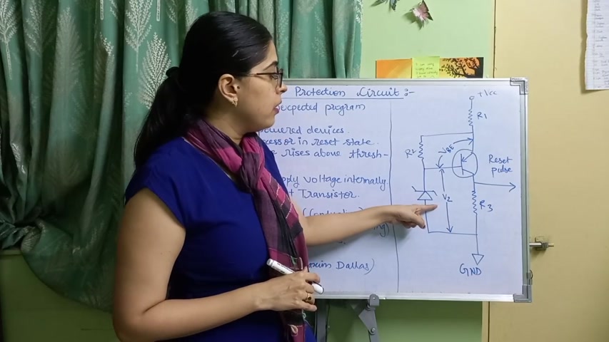
When the supply voltage VCC is lesser than the voltage across transistor and voltage across the Zener diode .
Okay .
Then it is less than the sum .
It stops conducting .
Okay .
And when it stops conducting , the voltage develops across the transistors .
Low current is flowing through it .
And when the voltage drop develops across the transistor , it indicates the active high .
So what are we getting initially ?
There was active low , then there was active high .
So we will get the reset ones like this .
Okay .
So this is the working of the Brownian protection circuit .
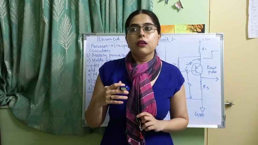
Now , there are , components in this circuit , resistor 1 , 2 , and 3 .
Now what are the values of these resistances ?
Values of the resistance r 1 , r 2 , and r 3 depends on the electrical characteristics of the transistor .
Electrical characteristics of the transistor .

What is the electrical characteristics of the transistor ?
It's , voltage and current ratings .
Okay .
Voltage and current ratings of the transistor .
So , voltage and current ratings , we can get from the datasheet of the transistor .
Okay .
And according to those ratings , we have the value of r 1 , r 2 , and r 3 .
Okay .
We are selecting the values according to the transistor .
Fine .
So , what are the examples of this Brownian protection circuit ?
See , this Brownian protection circuit is also called as a microprocessor supervisor IC .
An example of it is from Maxim Delas , IC DS 123 2 .
IC DS 12 32 from Maxim Delas is example of the Browner protection circuit .
I see .
So it is very important part .
Okay .
I hope you have understood this Browner protection circuit and you have liked this video .
So please like , share and subscribe my channel .
Thank you for watching .
Are you looking for a way to reach a wider audience and get more views on your videos?
Our innovative video to text transcribing service can help you do just that.
We provide accurate transcriptions of your videos along with visual content that will help you attract new viewers and keep them engaged. Plus, our data analytics and ad campaign tools can help you monetize your content and maximize your revenue.
Let's partner up and take your video content to the next level!
Contact us today to learn more.